AWS EKS: Deploying a Kubernetes cluster with a custom VPC configuration
Limits of default setup
Deploying a productive Kubernetes cluster on a cloud provider is a very straight forward task if you follow the guidelines and use default configurations. However, having a large enough custom use-case with specific scaling requirements can lead to system bottlenecks which require custom solutions to be resolved. Such is the case with the IP exhaustion which is unavoidable if your solution is scaling and you have used the default configuration supplied by eksctl.
In this blog post I will explain the exact steps needed to mitigate this issue in a simple and understandable way. More precisely you are going to learn:
- How to configure a custom VPC with public and private subnet for an EKS deployment
- How to make your VPC configuration scalable such that it allows extending the available IPs when needed
- Hands-on implementation of the AWS VPC infrastructure using terraform
- How to create an AWS EKS cluster and use the custom VPC inside of it using eksctl
Prerequisite
We are going to use eksctl to setup our cluster and terraform to create the infrastructure, so they should be installed on your system and configured to access your AWS subscription. In addition, general knowledge of networking and how the AWS VPC works is of advantage because this post will not conver the basics.
The IP exhaustion problem
If you have used a local Kubernetes cluster, such as Minikube or k3s, you are used to pods being assigned IP addresses from a large virtual network, typically isolated from your local network.
In comparison, a Kubernetes running as an EKS cluster uses the AWS VPC CNI (Container Network Interface) plugin to assign IP addresses which are directly taken from the VPC subnets.
Each pod in a Kubernetes cluster requires its own unique IP address and having not large enough VPC can set a limit on the number of concurrent pods that can run in your cluster. This could become a very unpleasant and unexpected problem once your productive workloads start to scale out and exceed the IP capacity of the VPC.
Therefore it is very important to setup your VPC in a way which covers your needs and leaves space for scaling and network extension.
EKS VPC Architecture
If you have used eksctl before, you should be familiar that it uses AWS CloudFormation under the hood to setup your EKS cluster. The tool provisions all of the needed infrastructure including the VPC. In general the VPC configuration looks like this:
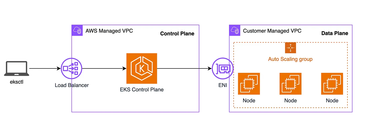
There are two VPCs that are created:
- AWS Managed VPC: Here reside the control plane nodes that run the Kubernetes software, such as etcd and the Kubernetes API server. This part of the infrastructure is completely managed by AWS.
- Customer Managed VPC: Here reside the node groups for the worker nodes running in our cluster. This is the VPC that we as AWS customers have to create and are responsible to configure and manage properly.
VPC Configuration
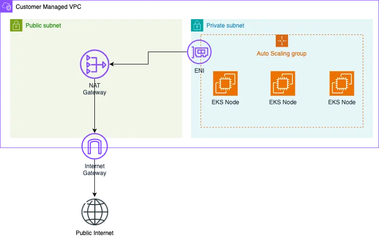
To comply with industry standards and allow for private and secure node provisioning we are going to create VPC with a Public and Private subnets. You can find more information for EKS subnet requirements on this page.
We are going to setup the following infrastructure:
-
The Private Subnet will host our EKS nodes so that they are not accessible from the internet. This ensure that these node will not have a public internet IP and require additional infrastructure if the need to fetch data from the internet. In layman’s terms, hosting your web server on these nodes will make them inaccessible for your clients. Feel free to reach out if you need to setup publicly accessible nodes in your cluster. Contact details are provided below.
-
The Public Subnet will contain a NAT gateway that will route all of the outbound traffic from the nodes in the private subnet to a internet gateway so that they can fetch data from the outside internet. Skipping this part of the infrastructure will make an air-gapped cluster which is isolated from the public internet.
Terraform VPC Setup
Let’s implement this in terraform. For the example we are going to use the CIDR block 10.0.0.0/20 which results in a total of 4096 IPs. We are going to split this range into 16 subnets (/24) each with a range of 256 IP. We can then assign a subset of those subnets to our VPC and extend it with more of them when needed. In addition to this we are going to create the subnets in two different availability zones for high availability.
Below is a configuration with 2 public subnets and 4 private subnets distributed symetrically across the availability zones A and B of region us-west-1. Create a file main.tf with the following content:
1
2
3
4
5
6
7
8
9
10
11
12
13
14
15
16
17
18
19
20
21
22
23
24
25
26
27
28
29
30
31
32
33
34
35
36
37
38
39
40
41
42
43
44
45
locals {
  cidr_block = "10.0.0.0/20"

  availability_zone_a = {
      name = "us-west-1a"
      public_subnets_cidrs = [
        "10.0.0.0/25",
      ]
      private_subnets_cidrs = [
        "10.0.1.0/24",
        "10.0.3.0/24",
      ]
    }

    availability_zone_b = {
      name = "us-west-1b"
      public_subnets_cidrs = [
        "10.0.0.128/25",
      ]
      private_subnets_cidrs = [
        "10.0.2.0/24",
        "10.0.4.0/24",
      ]
    }
}

provider "aws" {
  region = "us-west-1"
}

terraform {
  required_providers {
    aws = {
      source  = "hashicorp/aws"
      version = ">= 4.67.0"
    }
  }
  required_version = ">= 1.4.2"
}

resource "aws_vpc" "main" {
  cidr_block           = local.cidr_block
  enable_dns_hostnames = true
  tags                 = { Name = "eks-custom-vpc" }
}
Create a file called private.tf with the following content:
1
2
3
4
5
6
7
8
9
10
11
12
13
14
15
16
17
18
19
20
21
22
23
24
25
26
27
28
29
30
31
32
33
34
35
resource "aws_subnet" "private_subnet_a" {
  count             = length(var.availability_zone_a.private_subnets_cidrs)
  vpc_id            = aws_vpc.main.id
  cidr_block        = local.availability_zone_a.private_subnets_cidrs[count.index]
  availability_zone = local.availability_zone_a.name
}

resource "aws_subnet" "private_subnet_b" {
  count             = length(var.availability_zone_b.private_subnets_cidrs)
  vpc_id            = aws_vpc.main.id
  cidr_block        = local.availability_zone_b.private_subnets_cidrs[count.index]
  availability_zone = local.availability_zone_b.name
}

resource "aws_route_table" "private" {
  vpc_id = aws_vpc.main.id
}

resource "aws_route_table_association" "private_sn_association_a" {
  count          = length(aws_subnet.private_subnet_a)
  subnet_id      = aws_subnet.private_subnet_a[count.index].id
  route_table_id = aws_route_table.private.id
}

resource "aws_route_table_association" "private_sn_association_b" {
  count          = length(aws_subnet.private_subnet_b)
  subnet_id      = aws_subnet.private_subnet_b[count.index].id
  route_table_id = aws_route_table.private.id
}

resource "aws_route" "private_route_nat" {
  route_table_id         = aws_route_table.private.id
  destination_cidr_block = "0.0.0.0/0"
  gateway_id             = aws_nat_gateway.nat_gateway.id
}
Create a file called public.tf with the following content:
1
2
3
4
5
6
7
8
9
10
11
12
13
14
15
16
17
18
19
20
21
22
23
24
25
26
27
28
29
30
31
32
33
34
35
36
37
38
39
40
41
42
43
44
45
46
47
48
49
50
resource "aws_subnet" "public_subnet_a" {
  count                   = length(var.availability_zone_a.public_subnets_cidrs)
  vpc_id                  = aws_vpc.main.id
  cidr_block              = local.availability_zone_a.public_subnets_cidrs[count.index]
  map_public_ip_on_launch = true
  availability_zone       = local.availability_zone_a.name
}

resource "aws_subnet" "public_subnet_b" {
  count                   = length(var.availability_zone_b.public_subnets_cidrs)
  vpc_id                  = aws_vpc.main.id
  cidr_block              = local.availability_zone_b.public_subnets_cidrs[count.index]
  map_public_ip_on_launch = true
  availability_zone       = local.availability_zone_b.name
}

resource "aws_route_table" "public" {
  vpc_id = aws_vpc.main.id
}

resource "aws_route_table_association" "public_sn_association_a" {
  count          = length(aws_subnet.public_subnet_a)
  subnet_id      = aws_subnet.public_subnet_a[count.index].id
  route_table_id = aws_route_table.public.id
}

resource "aws_route_table_association" "public_sn_association_b" {
  count          = length(aws_subnet.public_subnet_b)
  subnet_id      = aws_subnet.public_subnet_b[count.index].id
  route_table_id = aws_route_table.public.id
}

resource "aws_route" "public_route_internet" {
  route_table_id         = aws_route_table.public.id
  destination_cidr_block = "0.0.0.0/0"
  gateway_id             = aws_internet_gateway.ig.id
}

resource "aws_internet_gateway" "ig" {
  vpc_id = aws_vpc.main.id
}

resource "aws_eip" "eip" {
  domain = "vpc"
}

resource "aws_nat_gateway" "nat_gateway" {
  allocation_id = aws_eip.eip.id
  subnet_id     = aws_subnet.public_subnet_a[0].id
}
Use the files to provision the infrastructure and that is it. If terraform has created the infrastructure successfully, you will have a VPC with a public subnet, private subnet, route tables and routes that allow outbound internet connection of the nodes in the private subnet.
If you need any more IPs, you can extend and update the VPC by extending the public or private subnet arrays with any of the remaining /24 subnets.
Creating the EKS Cluster
In this step we are going to create an EKS cluster with the custom nodes and assign a node group to the private subnet.
We have to find out the ID of the VPC we have created. To do this either use the AWS console or execute the following CLI command:
aws ec2 describe-vpcs --filters "Name=tag:Name,Values=eks-custom-vpc" --query 'Vpcs[0].VpcId' --output text
Note down the ID of your VPC and use it in the following command to find out the IDs of your subnets.
aws ec2 describe-subnets - filters "Name=vpc-id,Values=**YOUR-VPC-ID-HERE**" - output table
Use the IDs of the subnets together with the VPC ID to fill the following cluster-config.yaml file for the cluster creation with eksctl:
1
2
3
4
5
6
7
8
9
10
11
12
13
14
15
16
17
18
19
20
21
22
23
24
25
26
27
28
29
30
31
32
33
34
35
36
37
38
39
apiVersion: eksctl.io/v1alpha5
kind: ClusterConfig

metadata:
  name: test-cluster
  region: us-west-1
  version: "1.29"

vpc:
  id: "**YOUR-VPC-ID-HERE**"
  subnets:
    public:
      us-west-1a:
        id: "**YOUR-ID-OF-PUBLIC-SUBNET-A-1**"
      us-west-1b:
        id: "**YOUR-ID-OF-PUBLIC-SUBNET-A-2**"
    private:
      us-west-1a-1:
        id: "**YOUR-ID-OF-PRIVATE-SUBNET-A-1**"
      us-west-1b-1:
        id: "**YOUR-ID-OF-PRIVATE-SUBNET-B-1**"
      us-west-1a-2:
        id: "**YOUR-ID-OF-PRIVATE-SUBNET-A-2**"
      us-west-1b-2:
        id: "**YOUR-ID-OF-PRIVATE-SUBNET-B-2**"

managedNodeGroups:
  - name: example-compute
    instanceType: t3.large
    desiredCapacity: 3
    minSize: 0
    maxSize: 3
    spot: true
    privateNetworking: true
    subnets:
      - "**YOUR-ID-OF-PRIVATE-SUBNET-A-1**"
      - "**YOUR-ID-OF-PRIVATE-SUBNET-B-1**"
      - "**YOUR-ID-OF-PRIVATE-SUBNET-A-2**"
      - "**YOUR-ID-OF-PRIVATE-SUBNET-B-2**"
You can then proceed with the cluster cluster creation by executing:
eksctl create cluster -f cluster-config.yaml